
|
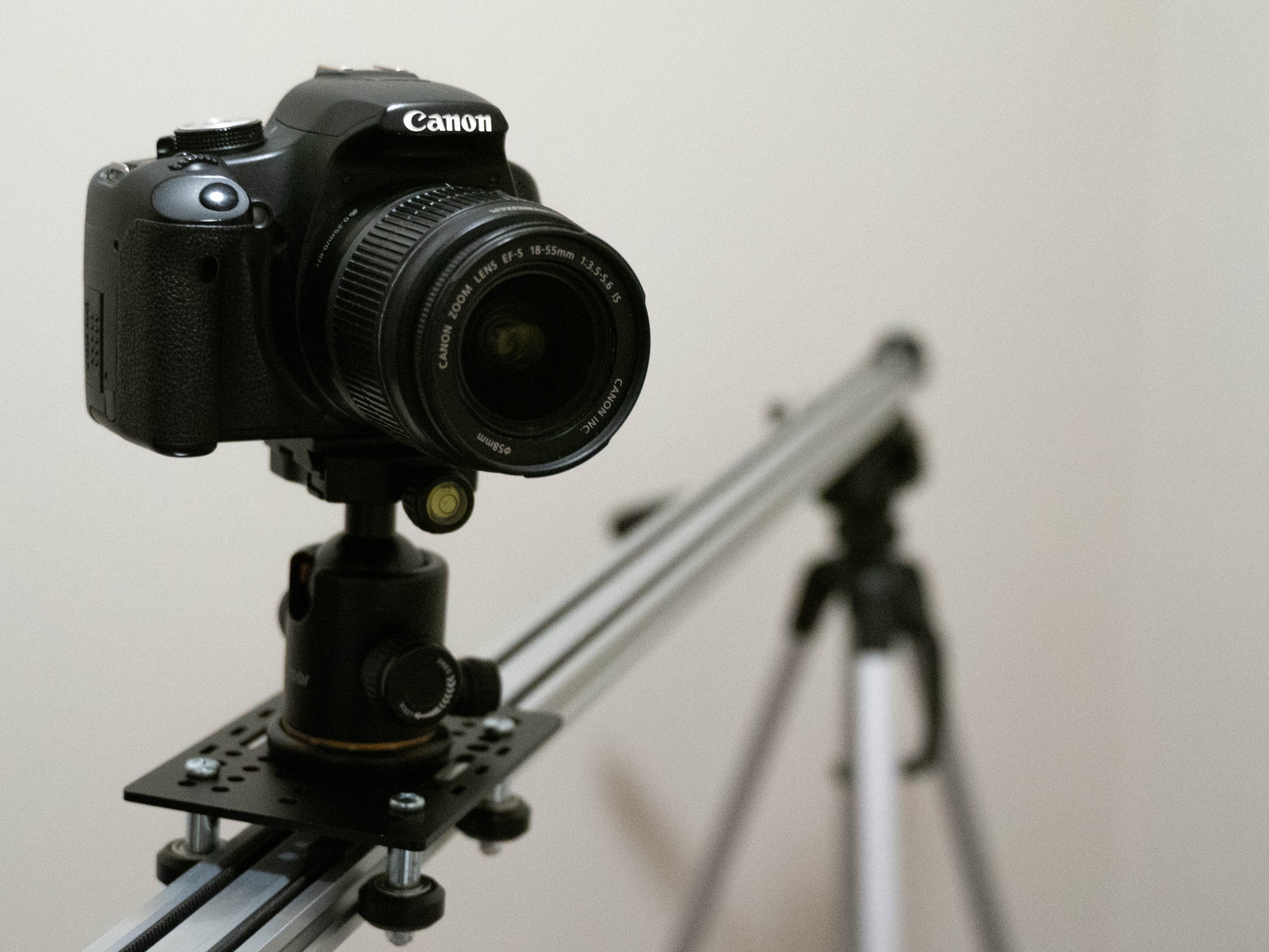
This project involved making a camera slider with motors added to it to slowly move a camera as it takes a time lapse. Everything is controlled by a Raspberry Pi including the movement of the motors as well as when the camera takes a picture. There is already software built for Linux that will interface with most cameras using shell commands. The challenges of this project were building the motorized slider, creating the software that would control the motors and the camera, and coming up with a way to interface with the Raspberry Pi even in remote locations away from power sources and internet. A motorized camera slider makes for an overall better, more dynamic time lapse; especially when it comes to things like astrophotography. |
Hardware
|
|
|
When the python script that controls the slider is run, the user is asked a series of questions to learn the settings for that particular time lapse. The software then checks if the camera is on/connected and also gets the camera’s shutter speed. Some calculations are then made and the time lapse is run according to the user’s specifications. Possible future additions include a second stepper motor that would allow the camera to rotate and a phone application with the ability to control the slider’s settings. Here is a link to the current version of the code used for the slider: slider.py Click here for the full project write up. |
|
|
|
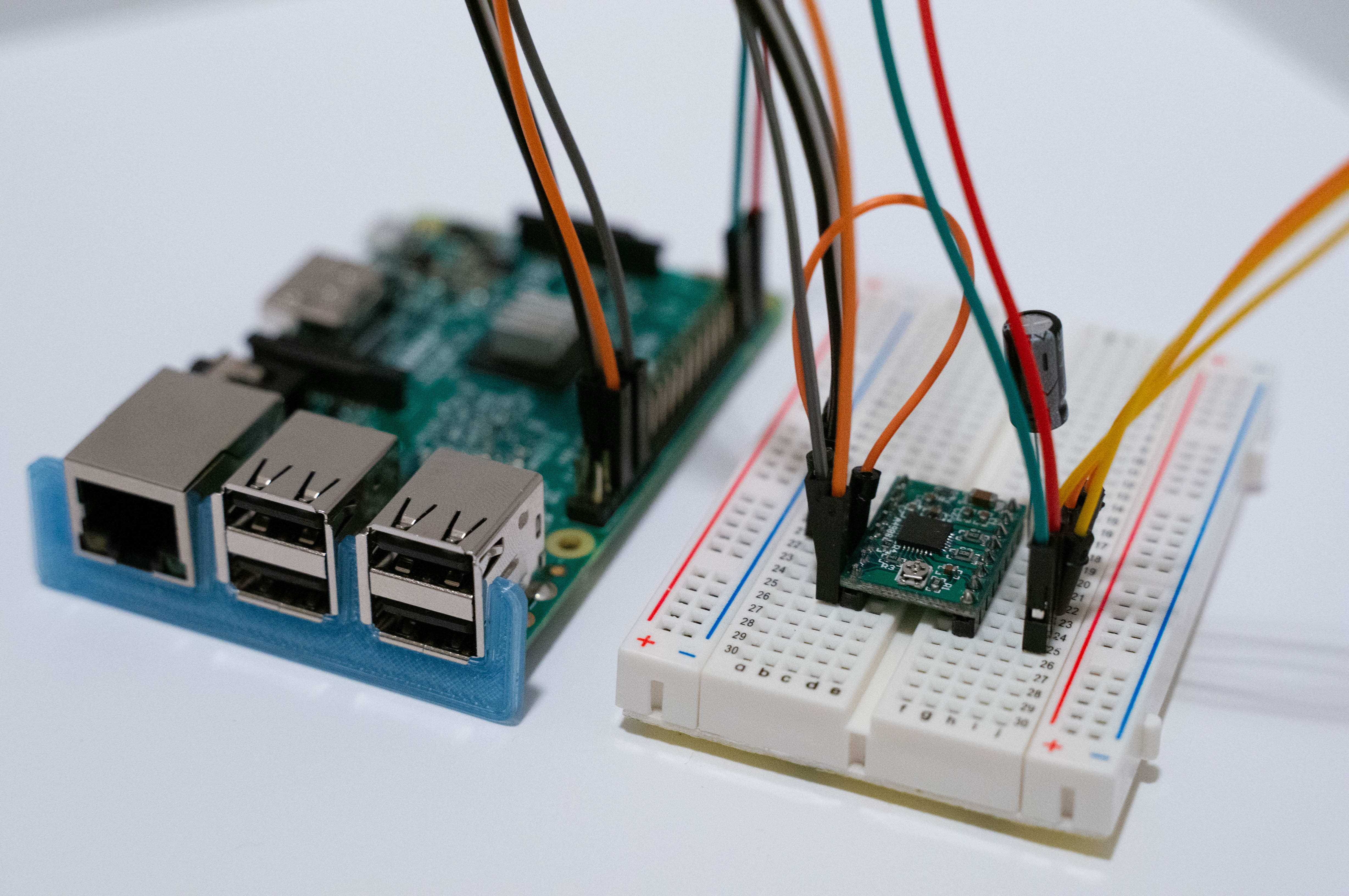
PART TWO: As you can see with the first version of my camera slider, there are a lot of wires which made things a bit cumbersome when trying to move the slider from location to location. For this reason I decided to design and build a printed circuit board (PCB) to eliminate the wires and make the camera slider much easier to set up and take down. |
|
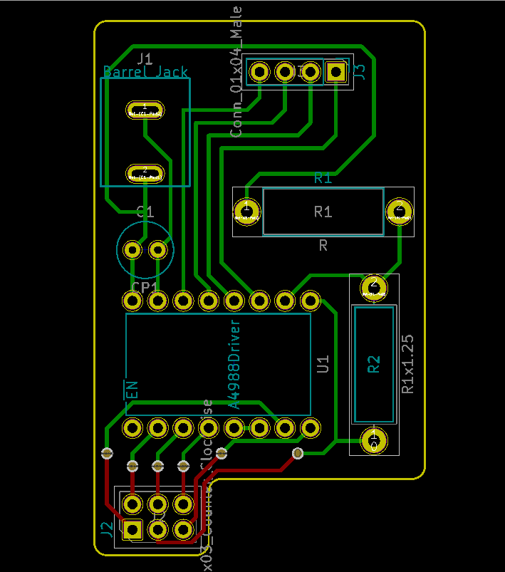
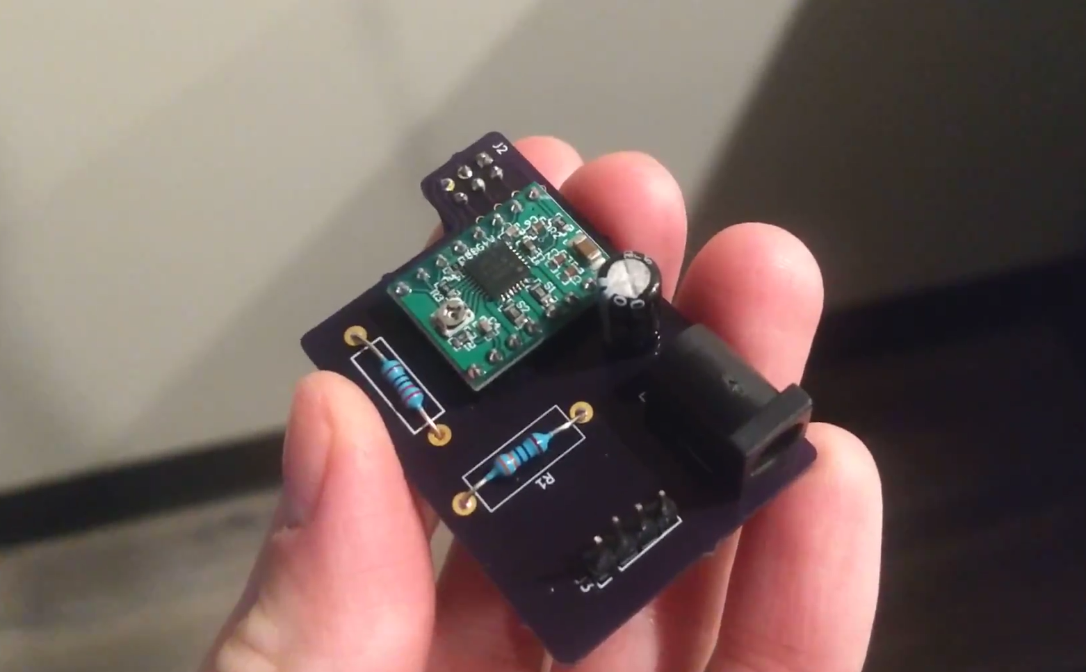
In order to build the PCB I first had to learn how to use the design software. I chose to use KiCad and, through hours of trial and error, I was finally able to create a solid design. I had to learn how to place parts in a way that the interconnects wouldn't get in the way of each other and that everything was placed in the most logical spot in the board. I used a company called OSH Park to print my design. All I had to do was upload the design files to there website, specify a few settings, and they sent me the finished product a couple of weeks later. After that, I soldered all of the parts to the board and ran test as I went to make sure everything was working properly.
|
|
|